Know More about BETAFPV ELRS Part II
ELRS Micro Module Temperature
We appreciate all of your valuable feedback on our ELRS Micro TX Module. We have received many reports from pilots telling us their concerns about the heat sink and loading capacitor.
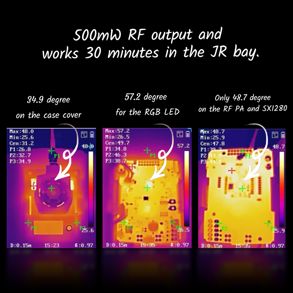
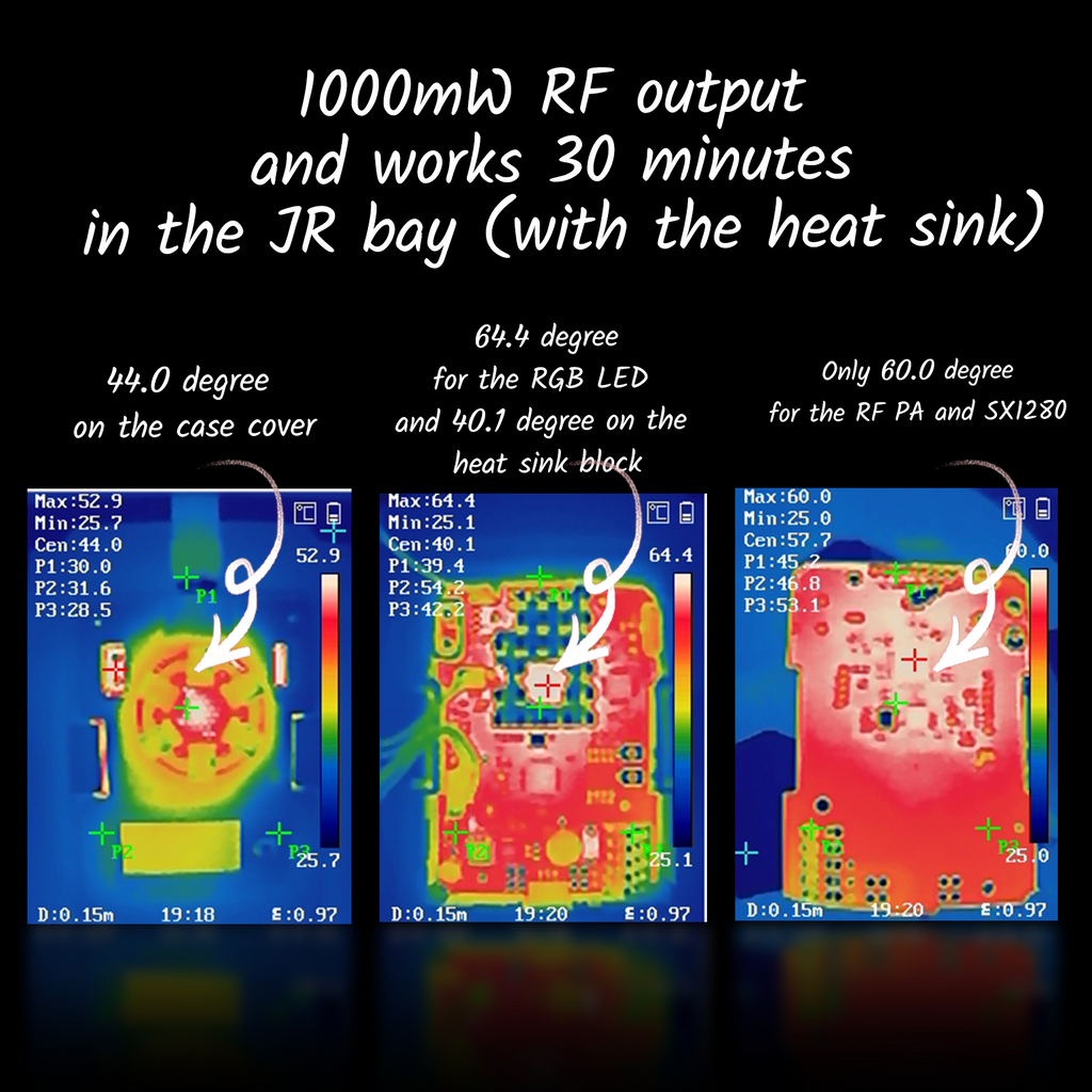
Currently, the RF module is installed on the backside of the baseboard, this had led to many questions about whether the module can cool down and stay secure? The reason why we have installed the RF module on the backside of the mainboard is to have enough space for the RGB LED and the heat sink (only needed for the next 1W version). We have tested the temperature of this setup; With 500mW maximum RF output and 30 minutes powering on, the temperature of the RF chip can be kept under 50 degrees Celsius and about 30 degrees for the case. It proves that the module can perform properly in daily use and need not to worry about the temperature. Also, for the black version (maximum 1W, upcoming in December), the temperature can be kept under 65 degrees, with a heat sink in our testing. Results are also showing that the temperature of the RGB LED would be 10 degrees higher for both 500mW and 1W RF module. This is the reason why the cooling fan component is needed in this situation.
ELRS Micro Module Heat Sink
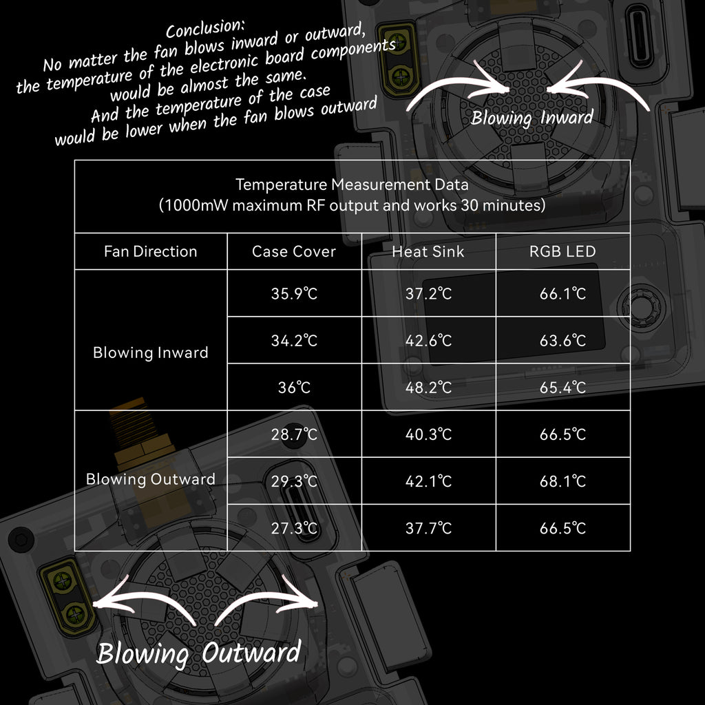
There are also questions raised should the fan be blowing air inward or outward. Our testing results show that the only temperature difference would be shown on the JR case, as the electronic components inside remain unaffected.
Loading Capacitors on Oscillator
On the F4 1S 5A FC (integrated SPI ELRS 2.4G receiver) prototype board, we have used a 20pF loading capacitor for the 52MHz oscillator. This will cause an unbinding issue with some modules. AlessandroAU and Jye Smith figured it out in the prototype board testing. Since then, we have changed it to 2-8pF and this loading capacitor value is suitable for this 52MHz oscillator in our testing. Hence, now all of the ELRS 2.4G products from BETAFPV come with a 2-8pF loading capacitor and should be compatible will all the ELRS items in the market.
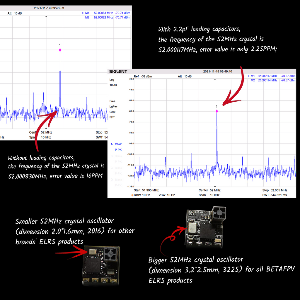
There is also a comparison made between the BETAFPV and other brands, on the use of loading capacitors on the Crystal Oscillator(CO) circuit. Currently on the market, many have removed the loading capacitors on their modules. In our case, we have chosen to use it due to the specification and layout of the CO which our module has. The normal CO is 2.0x1.6mm(2016), and BETAFPV’S ELRS products used a 3.2x2.5mm(3225)CO, which is bigger in size. Use the BETAFPV Lite receiver for example. When there are no loading capacitors included, the 52MHz crystal error value is 16PPM. When 2.2pF loading capacitors included, the error value would be 2.25PPM, more closed to the 52MHz value we needed. After repetitive testing, we came to the conclusion that the TX can correctly performs when the frequency error of 52MHz oscillator is lower than 40PPM, which we have successfully maintained. Ensuring the properly functioning of the SX1280 RF system.
Planning for the future, in order to achieve a better frequency precision and compatibility, we will decide whether to keep the CO or modify the capacitor under the circumstances of the specification, layout and temperature drift of the crystal oscillator in our later released products.
Thank you for your reading and support. This is the second statement of BETAFPV ELRS series. The next section will be "About the joystick and failsafe issue ", "Why Nano TX Module doesn't support WIFI?".


Leave a comment